
Motorcycle CarPlay Display Vibration Testing: What Buyers Should Ask For
Review motorcycle CarPlay display vibration evidence by configuration, mount, fixture, method, monitoring and acceptance criteria—without confusing a test method with a motorcycle qualification.
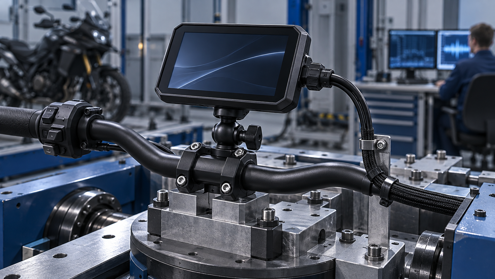
Motorcycle CarPlay display vibration testing is useful only when the evidence identifies the tested product configuration, mounting arrangement, excitation method, functional monitoring and acceptance criteria. A buyer should ask for more than a statement that a device is “vibration-tested”: request the report or a bounded summary that connects the screen, bracket, fasteners, connectors and cable routing to the way customers are expected to install and use the product. The purpose is not to demand one universal test profile. Motorcycle type, mounting location, accessory stack, operating conditions and intended market can change the engineering question. A disciplined review therefore starts with the use case, agrees a representative setup with the supplier, and records what the test does—and does not—support.
For importers and distributors, the practical decision is whether the available evidence supports the product claims, installation instructions and target customer segment. A test method is not itself proof of a specific vehicle fitment or a promise of service life. It is one controlled input to a product validation plan.
What vibration validation is intended to reveal
Vibration validation exposes an assembled product or component to defined mechanical motion while specified observations are made. For a handlebar-mounted display, the relevant assembly can include the display housing, ball joint, clamp, handlebar or representative fixture, fasteners, power connector, cable restraint and any camera or accessory lead. The goal is to identify risks such as loosening, intermittent electrical contact, cable wear, cracked or displaced parts, degraded display operation, or a mount that no longer holds its intended position.
The load path matters. Motion enters through the motorcycle or test fixture, passes through the handlebar and mounting hardware, and reaches the display enclosure and internal components. An adapter, extension arm, rubber isolator, alternate clamp or longer cable can change that path. Consequently, a test on a bare display or a rigidly clamped housing may not represent the shipped kit in its customer installation.
Vibration is also only one part of durability. Temperature, water exposure, dust, corrosion, impact, UV exposure, installation torque, handling and repeated adjustment can interact with mechanical loads. Buyers should treat a vibration report as one piece of evidence within a broader validation and quality system—not as a complete durability claim.
Start with the intended installation, not a borrowed profile
Before reviewing a test plan, define the intended use. Is the product designed for a supplied handlebar clamp, a particular bar diameter range, a crossbar, a mirror stem, or an optional extension? Is the display positioned close to the clamp or on a longer arm? Does the kit include a camera or separate control? How should the cable be routed and restrained? Which fasteners and torque instructions are part of the approved configuration?
These details determine what a representative setup means. If the final configuration is not decided, validation can still proceed in stages, but the report should describe the provisional setup and the change-control rule for later revisions. A supplier should not imply that evidence from one fixture automatically covers every mount, vehicle, accessory or installation.
| Buyer question | Evidence to request | Why it matters |
|---|---|---|
| What exact assembly was tested? | SKU, hardware revision, mount, fasteners, cables and accessories | Establishes configuration boundaries |
| How was it attached? | Fixture drawing or photos, contact points, orientation and tightening method | Shows whether the setup represents the intended load path |
| What vibration was applied? | Method, axis, profile source, frequency range, control point and duration | Makes the test reproducible and interpretable |
| What was monitored? | Power, display function, connector continuity, movement or other agreed observations | Connects exposure to product behavior |
| What counted as a pass or failure? | Pre-agreed acceptance criteria and post-test inspection | Prevents an undefined “passed” conclusion |
| What changed after testing? | Deviations, corrective actions, retest scope and approved baseline | Shows whether the released product matches the evidence |
The values themselves should be selected by qualified engineering based on the product, use case and available evidence. Buyers should not copy a severity profile from a different product category merely because a supplier has used it before.
Separate test method from requirement
Standards are easy to misread when a document title sounds relevant. ISO 16750-3:2023 addresses mechanical loads for road-vehicle electrical and electronic equipment, but the ISO scope explicitly says the document is not intended to apply to environmental requirements or testing for systems and components of motorcycles and mopeds. It should therefore not be presented as a motorcycle display certification or as automatic proof of motorcycle suitability. If a supplier references it, ask which parts, if any, are being used as an engineering reference and what motorcycle-specific rationale defines the actual requirement.
IEC 60068-2-64 describes a broadband random vibration test method. A method explains how a test can be conducted; it does not by itself select the correct severity, mounting condition, operating state, acceptance criteria or market qualification for a particular motorcycle display. Ask the supplier to distinguish clearly among: the method used, the product-specific requirement, the source or rationale for the profile, and the conclusion supported by the result.
The same principle applies to any standard or customer specification. Check its edition, scope, exclusions, test configuration and intended claim. A report can demonstrate that a sample was exposed under stated conditions. It does not automatically establish that every production lot, vehicle, mount or operating environment has been qualified.
Review the report as a chain of evidence
An actionable report lets a reviewer trace the path from requirement to disposition. It should identify the sample and configuration, test equipment or control approach at an appropriate level, fixture and orientation, applied profile, exposure sequence, monitoring, observations, deviations and final assessment. The buyer does not necessarily need proprietary design details; a supplier can provide a controlled summary while retaining confidential information. But the summary should still allow the buyer to understand the scope and limitations.
Ask whether the unit was powered during exposure, whether the display or connection was monitored continuously or at defined checkpoints, and whether the evaluation included function before and after exposure. Clarify what physical inspection covered: fasteners, joints, enclosure, screen retention, sealing features, connector engagement, cable jacket and strain relief. If a failure occurred, request the failure description, containment decision, corrective action and evidence that the corrective configuration was retested as required.
Do not reduce acceptance to “no visible damage.” A mount can look intact while shifting under load; an intermittent contact may not appear in a brief power-on check; a connector can remain seated while its cable is damaged nearby. Conversely, cosmetic movement may not be a functional failure if the approved criteria allow it. Define observations and limits before exposure, and record the decision owner.
A buyer-side review workflow
Use this sequence during supplier qualification or sample approval:
- Define the claim. State what you need to support: a particular mounting kit, target use, function during exposure, or post-test condition. Avoid vague claims such as “motorcycle grade.”
- Freeze the sample identity. Record SKU, hardware revision, firmware if relevant, mount parts, cable length, accessories and installation instructions.
- Agree the representative setup. Review mounting points, orientation, fasteners, torque, fixture, cable restraint and any intentional isolation.
- Approve the engineering plan. Confirm method, profile rationale, axes, operating state, monitoring points, sequence and acceptance criteria with responsible engineering and quality reviewers.
- Review execution and deviations. Match the report’s tested configuration to the approved sample; investigate substitutions, interruptions or fixture changes.
- Connect result to release. Decide whether evidence supports the defined claim, whether corrective work or retest is required, and how changes will be controlled.
This workflow is a decision aid, not a universal certification recipe. The supplier and buyer should agree the technical severity and acceptance criteria for the specific product and intended use.
Connect validation to manufacturing quality
A successful engineering sample does not guarantee consistent production. For launch readiness, ask how the approved configuration flows into the control plan: mount and fastener specifications, connector and harness checks, assembly instructions, torque tools where applicable, inspection criteria, traceability and change notification. Determine whether incoming components, in-process assembly and finished goods each have defined controls, and who owns nonconforming product disposition.
Also ask what changes trigger impact assessment. A different bracket material, supplier, fastener, cable routing, enclosure, display mass, firmware behavior, packaging or installation instruction can affect the evidence boundary. The supplier should have a documented way to assess whether the change needs engineering review, partial testing, full retest or no new vibration work, with a rationale recorded. This is a quality-system question, not simply a request to repeat one test for every revision.
For distributors, this connection helps prevent an approved sample from drifting into a different commercial configuration. Link the validation summary to the exact SKU and approved bill of materials, and make sure product pages and sales materials do not claim broader compatibility or durability than the evidence supports.
Common gaps in supplier evidence
- A certificate-like statement without the actual method, scope or report identifier.
- A report that names the display but not its mount, fixture or cable arrangement.
- A profile with no source or engineering rationale.
- No recorded functional monitoring or post-test criteria.
- Results from a prototype whose hardware differs from the current quotation.
- A corrective action described without retest or release linkage.
- A broad “motorcycle compatible” claim derived from one setup.
- No process for evaluating configuration changes after approval.
These gaps do not prove a product is defective. They mean the buyer cannot yet determine what the evidence supports. Ask a focused follow-up question and decide whether the risk is acceptable, needs a bounded pilot, or requires additional validation before making a market claim.
FAQ
Does a vibration test prove a motorcycle display will never fail?
No. A test is bounded by its sample, configuration, profile, duration, monitoring and acceptance criteria. It can provide evidence about defined risks, but cannot guarantee every vehicle, installation, road condition or service life.
Can a car electronics standard be used for a motorcycle display?
It may be referenced as an engineering input only when its scope and exclusions are understood. ISO 16750-3:2023 explicitly excludes motorcycle and moped systems and components from its intended application. Ask the supplier to explain the product-specific basis for any method or profile.
What should a distributor request if the full report is confidential?
Request a controlled summary identifying the tested SKU and mount, fixture and orientation, method and profile rationale, monitoring, acceptance criteria, deviations, outcome and limitations. Sensitive parameters can be redacted if the remaining evidence still supports the decision.
Should the mount and display be tested together?
If the mount is part of the supplied or claimed installation, the test plan should consider the assembled load path. Engineering may also test components separately to isolate risks, but component-level evidence should not be mistaken for assembled-system evidence.
Does a pass mean every motorcycle fitment is supported?
No. Fitment, bar geometry, attachment hardware, cable routing and accessory stacks can differ. A pass applies only within the report’s stated configuration and criteria unless further evidence extends that boundary.
Related reading and next step
For adjacent product and channel context, see the motorcycle CarPlay channel strategy for distributors and motorcycle CarPlay display vs. phone mount comparison. Explore relevant product categories and OEM/ODM capabilities when assessing a private-label or distribution program.
If you are qualifying a motorcycle display program, request a Motorcycle Display Validation Review. Share the intended mount, target rider or channel, installation assumptions and evidence questions; ask the supplier to map the available validation summary to that scope before you approve product claims or launch quantities. Discuss your program with TrolinkTek.
Author: TrolinkTek Editorial Team · Published: October 13, 2026 · Updated: October 13, 2026
Sources and scope notes
- ISO 16750-3:2023, Road vehicles — Environmental conditions and testing for electrical and electronic equipment — Part 3: Mechanical loads. Consult the scope and exclusions before citing it for a motorcycle application.
- IEC 60068-2-64, Environmental testing — Test Fh: Vibration, broadband random and guidance. A test method does not select a product-specific motorcycle requirement.